Installation guide for the Aluacero P59×35 panel on a metal structure, covering fixings, joints, corners and frame installation.
Supports and wind resistance
The installer or designer designs the metal support structure. Support spacing depends on the design wind pressure, material, panel type and support arrangement.
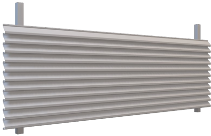
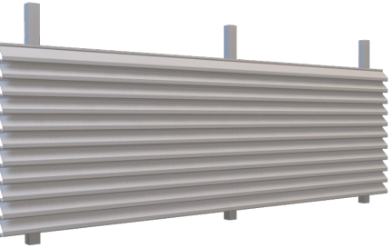
0.6 mm steel
| Spacing between supports (m) | Solid | With openings | Microperforated | Multiperforated | EOLO | |||||
|---|---|---|---|---|---|---|---|---|---|---|
| 2 supports | 3 supports | 2 supports | 3 supports | 2 supports | 3 supports | 2 supports | 3 supports | 2 supports | 3 supports | |
| 1 | 400 | 400 | 400 | 400 | 400 | 400 | 400 | 400 | 320 | 400 |
| 1.25 | 400 | 400 | 400 | 400 | 400 | 400 | 400 | 400 | 250 | 360 |
| 1.5 | 360 | 400 | 400 | 400 | 390 | 400 | 325 | 400 | 190 | 305 |
| 1.75 | 225 | 245 | 280 | 400 | 245 | 360 | 200 | 315 | 150 | 260 |
| 2 | 150 | 260 | 185 | 315 | 160 | 275 | 135 | 230 | 100 | 215 |
| 2.25 | 105 | 205 | 130 | 250 | 115 | 210 | 95 | 190 | 85 | 175 |
| 2.5 | 75 | 160 | 95 | 200 | 80 | 170 | 70 | 150 | 65 | 140 |
| 2.75 | 55 | 135 | 70 | 160 | 60 | 140 | 50 | 120 | — | 110 |
| 3 | 45 | 110 | 55 | 130 | 45 | 115 | 40 | 95 | — | 90 |
0.8 mm aluminium
| Spacing between supports (m) | Solid | With openings | Microperforated | Multiperforated | ||||
|---|---|---|---|---|---|---|---|---|
| 2 supports | 3 supports | 2 supports | 3 supports | 2 supports | 3 supports | 2 supports | 3 supports | |
| 1 | 400 | 400 | 400 | 400 | 400 | 400 | 400 | 400 |
| 1.25 | 270 | 400 | 310 | 400 | 270 | 400 | 215 | 400 |
| 1.5 | 155 | 350 | 180 | 400 | 155 | 350 | 125 | 285 |
| 1.75 | 100 | 240 | 110 | 275 | 100 | 240 | 80 | 190 |
| 2 | 65 | 160 | 75 | 180 | 65 | 160 | 50 | 126 |
| 2.25 | 45 | 110 | 55 | 130 | 45 | 110 | 35 | 90 |
| 2.5 | 30 | 80 | 35 | 95 | 30 | 80 | 25 | 65 |
Installation on a metal structure
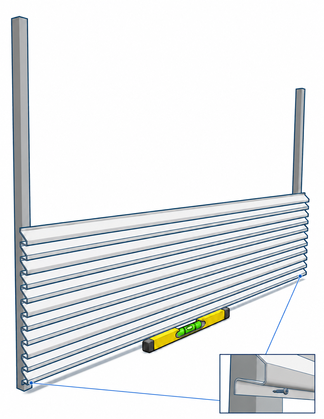
1. Level the bottom edge of the panel and fit the lower screws
Place the spirit level against the bottom edge of the first panel. Once level, fit the lower self-drilling screws into the posts.
2. Check the 650 mm dimension
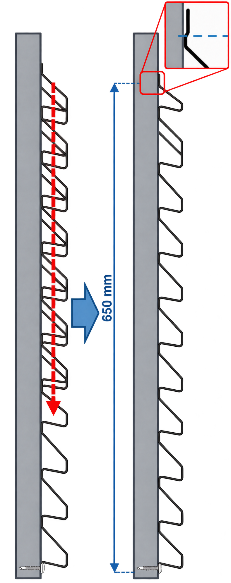
Check the 650 mm dimension at the points shown in the drawing and adjust the panel if necessary.
3. Fit the remaining screws
Fit the remaining self-drilling screws at the points shown in the drawing.
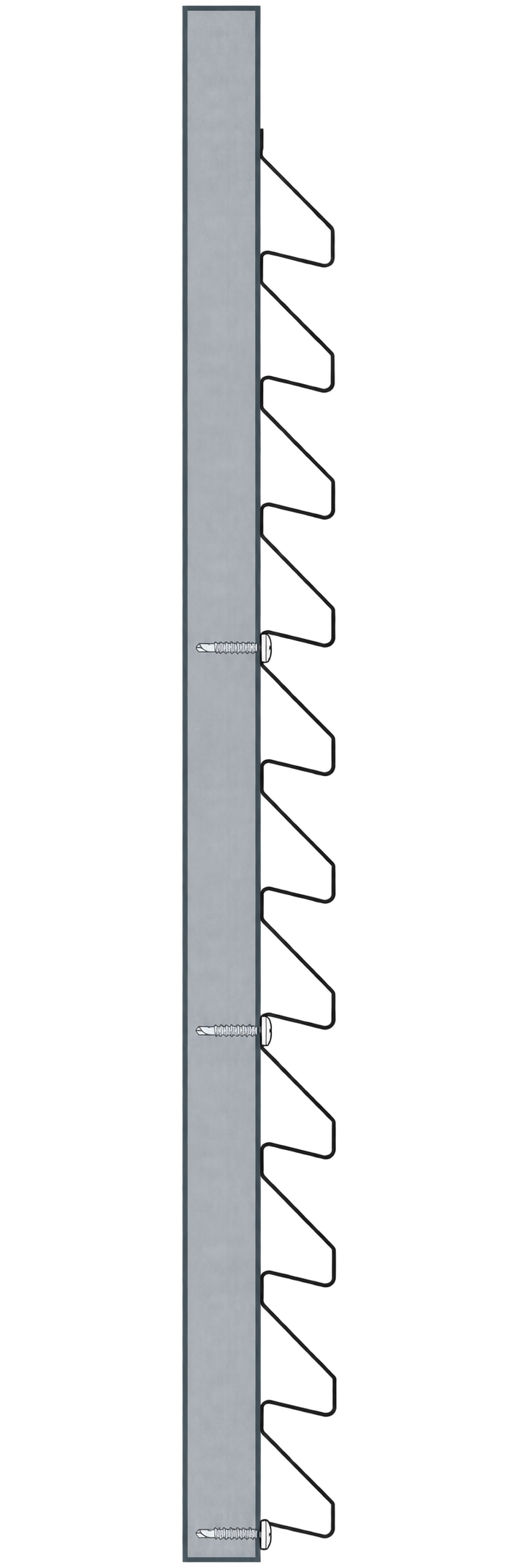
4. Fixing the remaining panels
Install the panels from the bottom up and fix them using the same method.
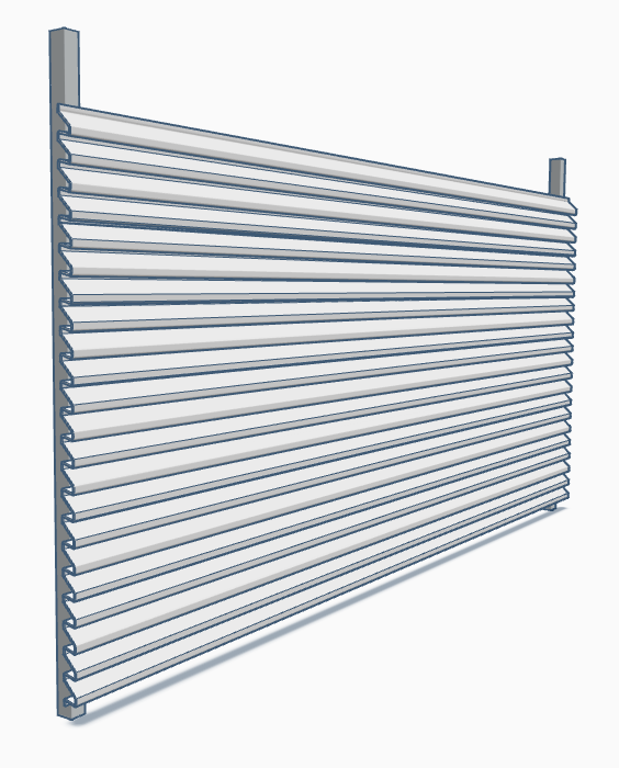
Panel joints
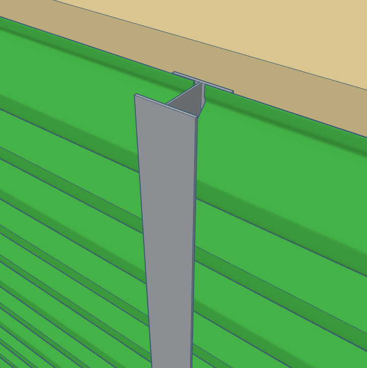
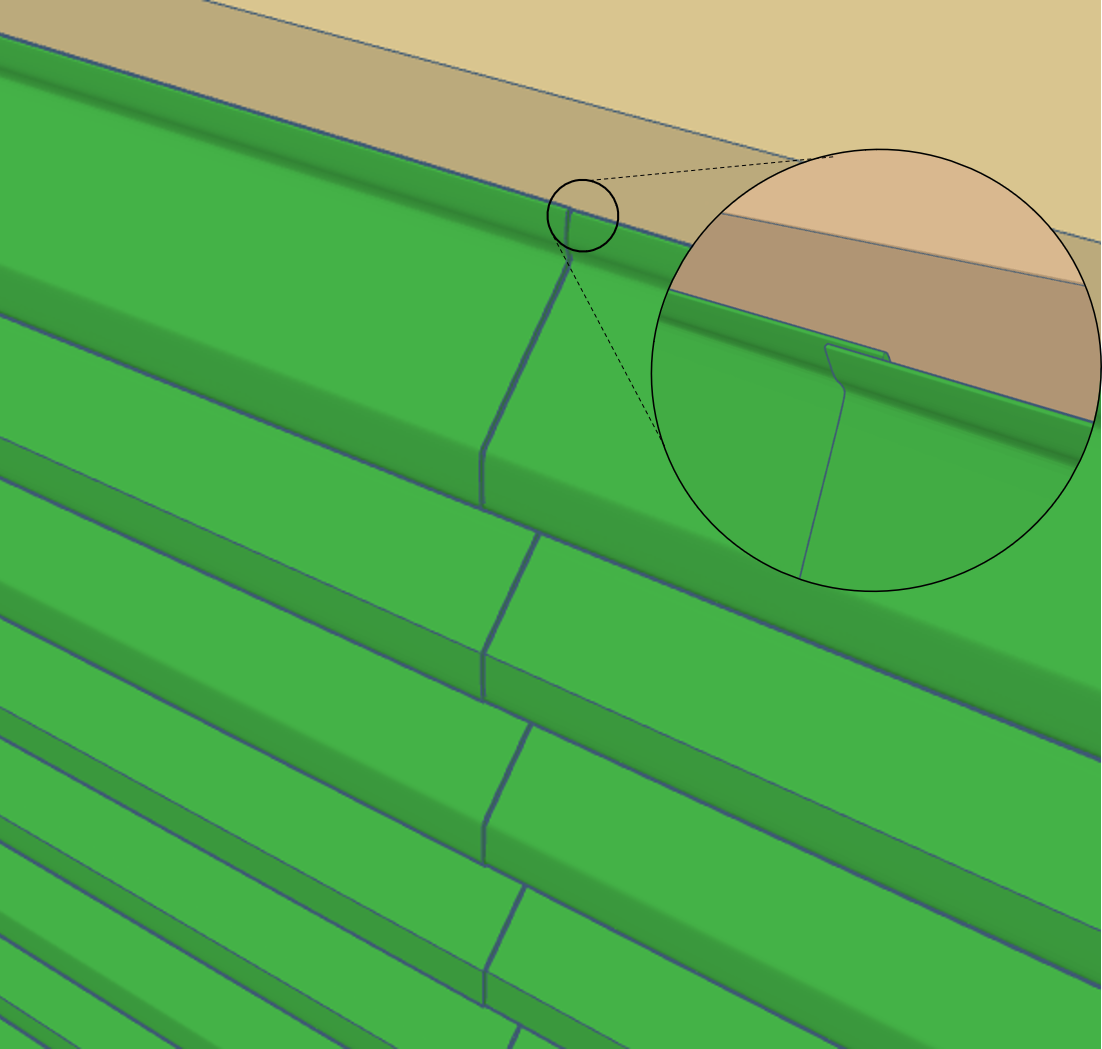
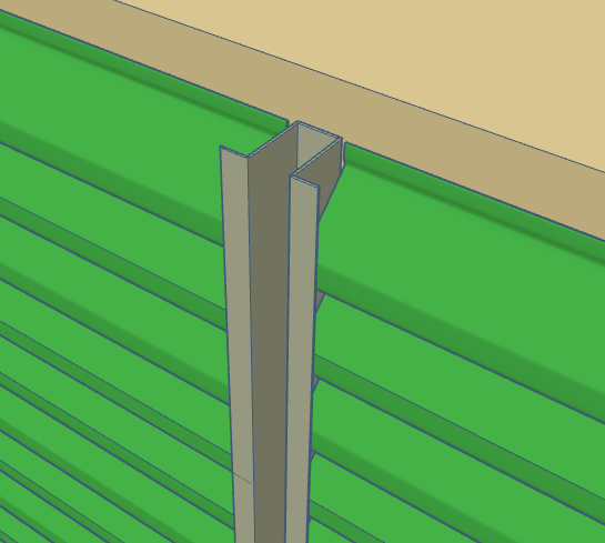
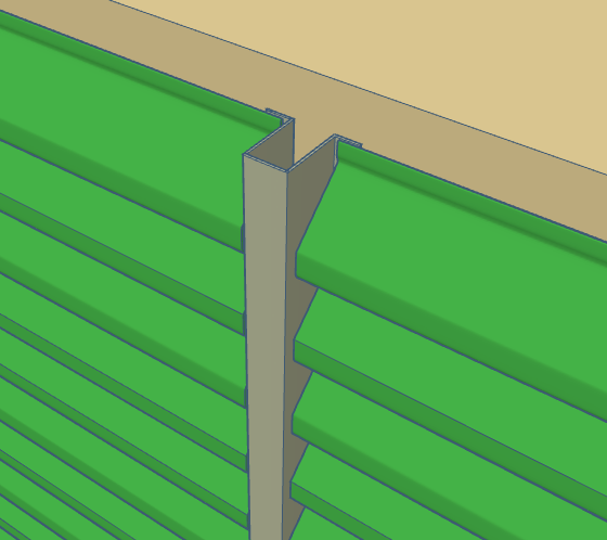
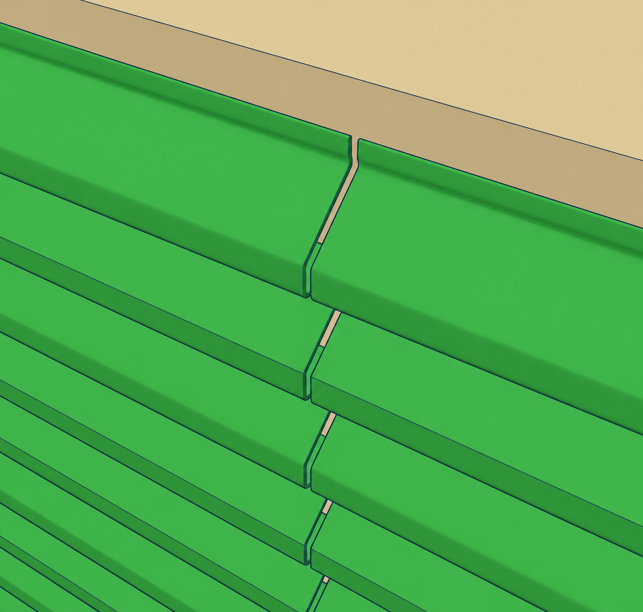
Corner details
Clip-on corner trim
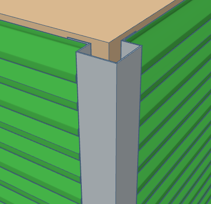
- Fix the panel and cross bracket with self-drilling screws.
- Fit the corner trim onto the bracket. The trim can be curved or square (90°).
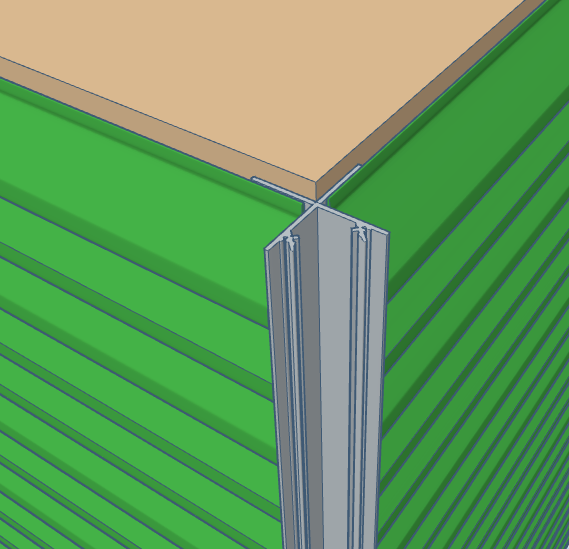
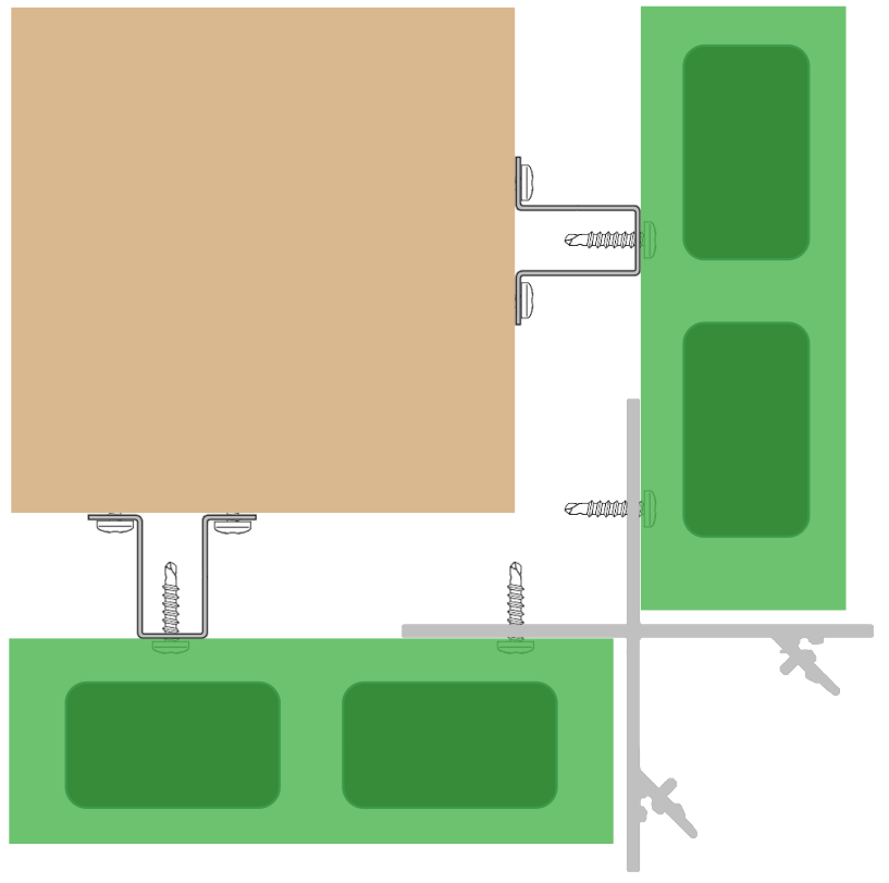
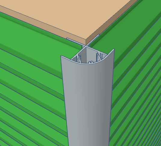
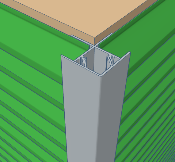
View the corner assembly in 3D
Other trims
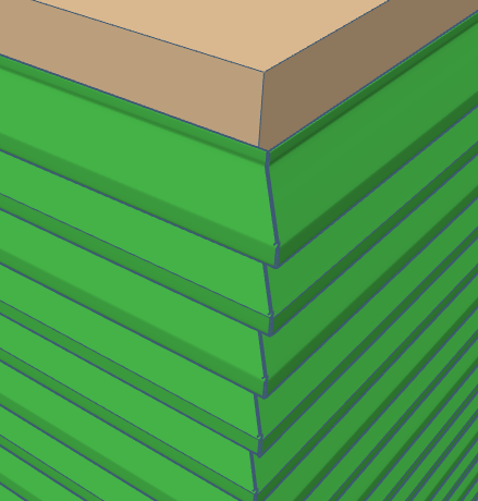
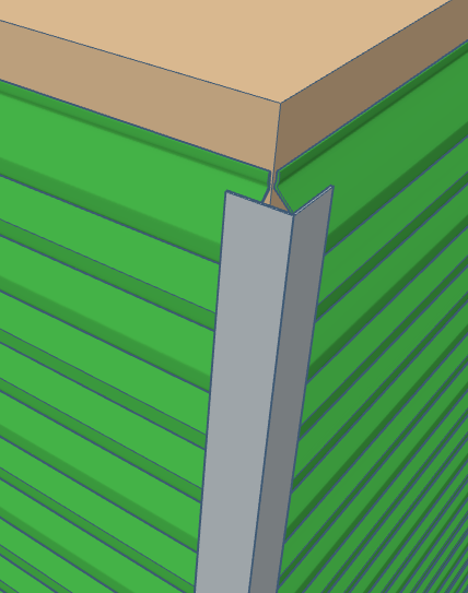
The mitre cut is shown as a finishing example. Cierres del Hogar does not supply mitre-cut Aluacero panels.
Installation in a P60 frame
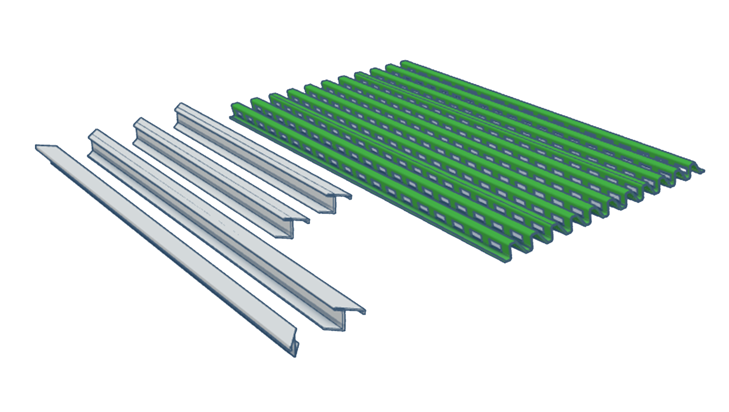
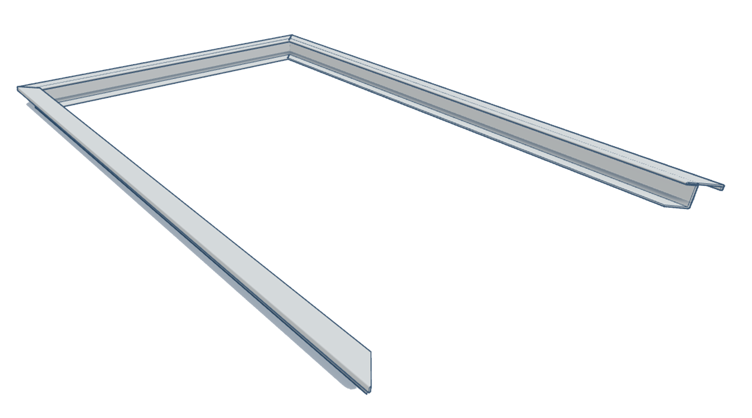
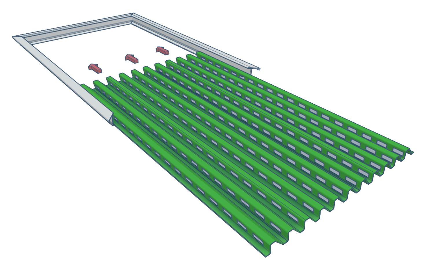
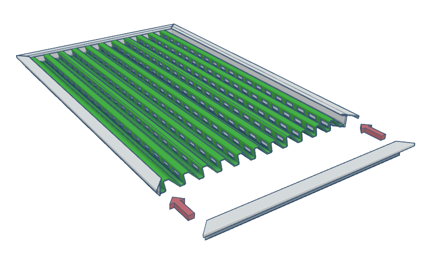
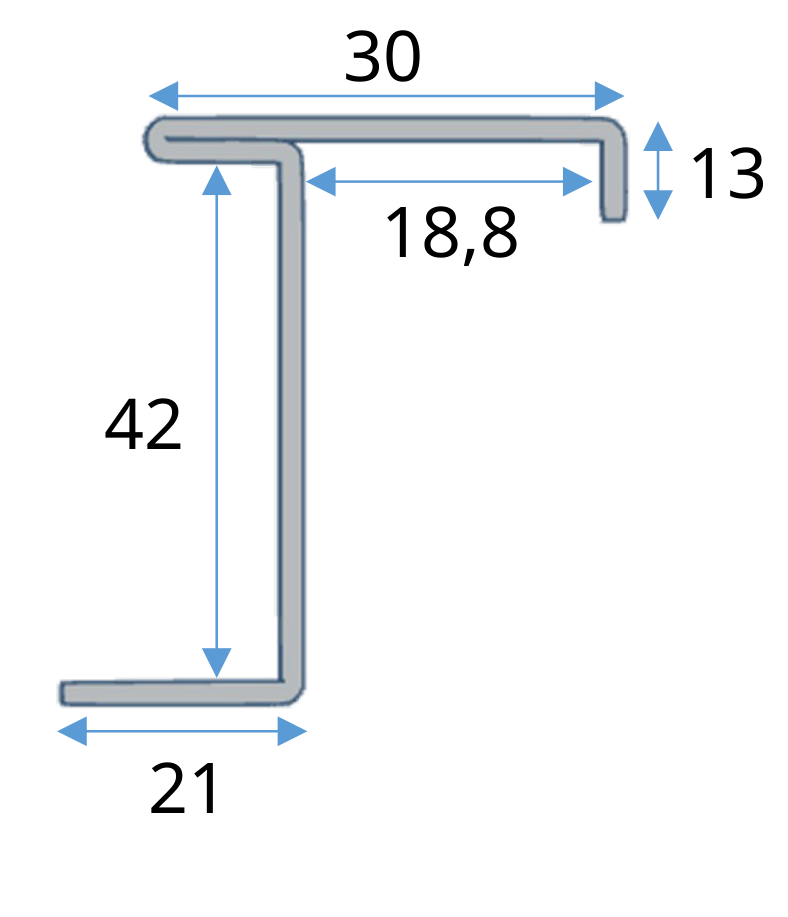
Installation in a U-channel
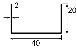
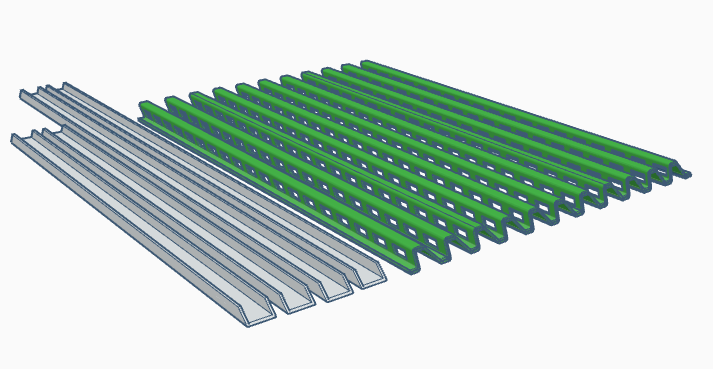
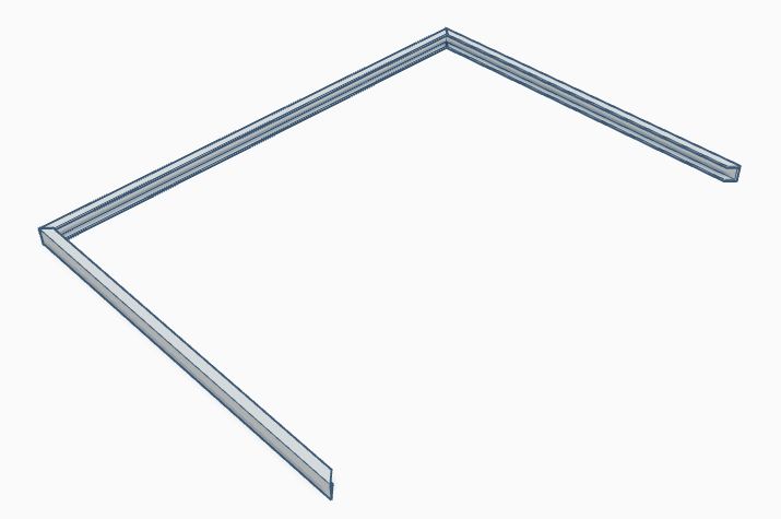
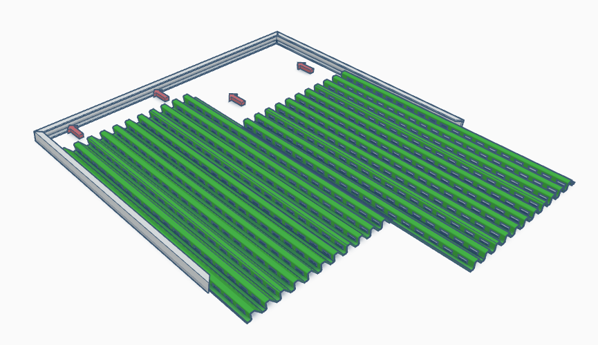
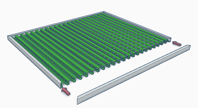
3D installation examples
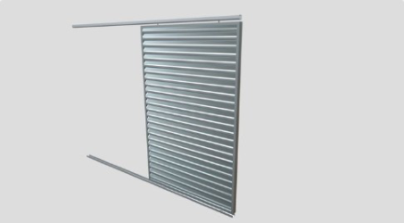
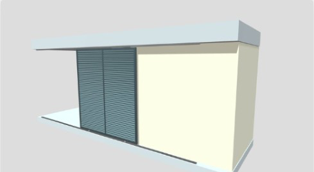
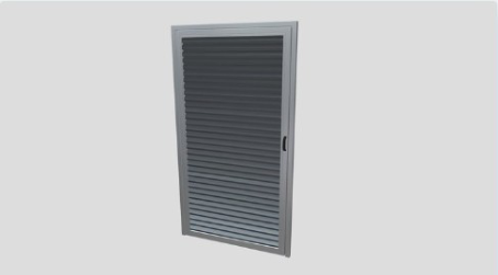
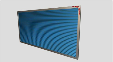
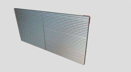
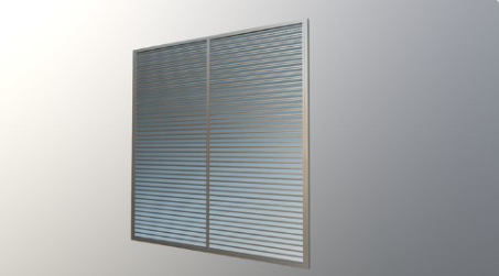
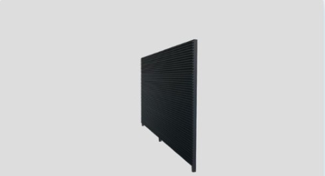
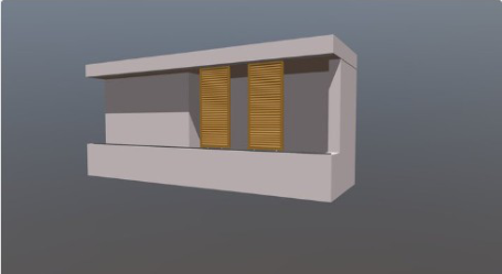
Select an example to open the interactive model in Sketchfab in a new tab.